


Document Actions
gvSIG Mobile 0.3. User guide
The editing tools are used to create new geometries in previously loaded vector layers. Three types of geometries can be created:
- Points Created with the Point tool (1).
- Lines Created with the Line tool (2).
- Polygons Created with the Polygon tool (3).
There are also editing tools for creating geometries using information from a GPS:
- (Waypoint) Add points with the Add vertex using GPS tool (4).
- (Track) Add a trail of points with the Add vertices automatically using GPS tool (5). Points are captured according to a specified time interval.
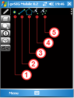
Editing toolbar
With the editing tools, vector layers can be updated with new data created by the user. Any new geometries automatically inherit the attributes of the layer being edited. These attributes can be entered once the geometry or feature has been digitised.
The procedure for editing an existing vector layer is as follows:
- Step 1 - Enable Editing: Once a layer has been loaded into the View (1), editing of the layer is enabled in the Table of Contents (hereafter referred to as TOC). As explained earlier in this manual, the TOC is opened from the Layers toolbar (2). To enable editing tick the checkbox (3) below the pencil icon of the layer that is to be edited. Return to the View by clicking the Accept button (4) to close the TOC.
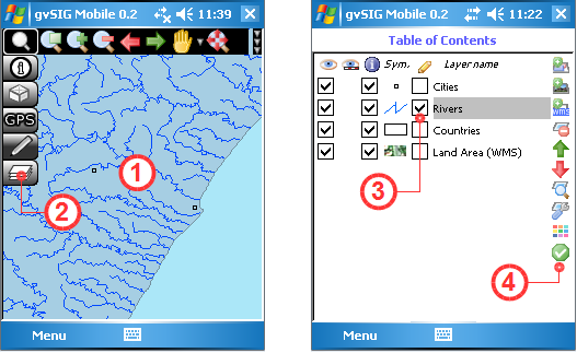
Enable editing of a vector layer
- Step 2 - Select the drawing tool: Select the appropriate drawing tool from the Editing toolbar (1). Note that if the layer being edited is a point layer, then only the Add point (2), Add vertex using GPS (5) and Add vertexes automatically using GPS (6) tools can be activated. For line layers only the Add line (3) and the GPS buttons mentioned above can be activated, while for polygon layers only the Add polygon tool (4) is available. For layers that support multiple geometries, for example GML layers, any of the drawing tools can be activated. When a tool is selected and activated for editing it is displayed with a yellow background.
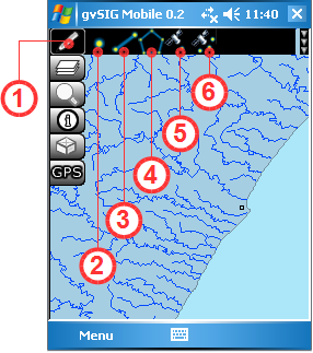
Activating editing tools
- Step 3 - Add New Geometries: Explanations of how to use the various drawing tools appear below.
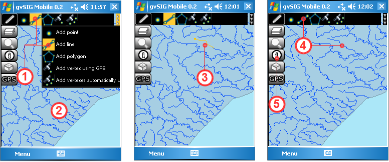
Add Point Tool:
Once the Add point tool (1) is activated, new points are added to the editable layer by clicking at the desired positions in the View (2). As many points as is needed can be digitised in this manner. New points are generated with the same attributes as in the layer being edited, except that these attributes are empty. To enter attribute data for a point first activate the Get Information tool (4) from the Information Management toolbar, then click on the new point to bring up the attributes form. Attributes can be entered using this form.
Adding points to a vector layer
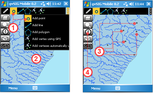
Add Line Tool:
Once the Add line tool (1) has been selected, a new line is created in the View (2) by digitising a series of points that define the line (3). While the line is being edited it is displayed in yellow (3) but once it has been completed it will be displayed in the same colour as the other lines in the layer. A line is completed by clicking the Add line tool again (4) or by "double-clicking". Care should therefore be taken when digitising a line as clicking too rapidly might be interpreted by the program as a double-click signifying completion of the line. Once the line has been completed attributes may be edited by using the Get Information tool (5) to bring up the attributes form for the new line feature. As with points, the new line inherits the same attribute fields as defined for the layer in which editing is taking place. Note that the attributes of a line cannot be entered until the editing of the line is complete. Bear in mind that any edits or changes can still be rejected by choosing not to save them to disk.
Adding lines to a vector layer
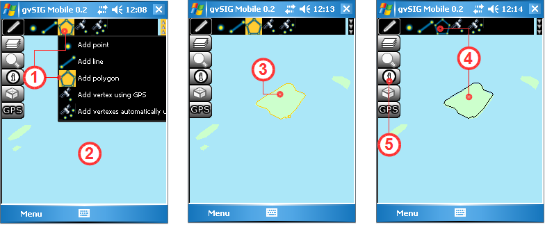
Add Polygon Tool:
After selecting the Add Polygon tool (1), start digitising the polygon in the View (2) by clicking a series of points to make up the shape of the polygon. As successive points of the polygon are digitised the outline of the polygon is shown in yellow (3). To finish editing the polygon, either "double-click" on the final point of the polygon or click the Add Polygon tool (4) again. The newly digitised polygon takes on the fill and outline colour properties of the layer into which it has been added. Once again, care should be taken not to digitise the polygon too quickly as rapid clicks might be interpreted as a double-click signifying completion of the polygon. Attributes can't be entered while the polygon is still being digitised. First complete the polygon and then bring up the attributes form with the Get Information tool (5). The attributes are inherited from the polygon layer being edited.
Adding polygons to a vector layer
Add Vertex using GPS Tool:
This tool, which requires a GPS to be connected and running, is easy to use. Simply click the Add Vertex using GPS tool (1) to add a new vertex using the current GPS position. The tool uses the GPS as a simple and effective means of creating reliable points, thereby eliminating possible errors that might be introduced when digitising "freehand".
Add Vertices Automatically using GPS Tool:
As with the previous tool, this one also requires the GPS to be connected and running before it can be activated. The tool facilitates the capturing of accurate point information from GPS readings, reducing possible errors that may arise from manual digitising of vertices. The main difference between the Add Vertices Automatically using GPS tool (1) and the previous one is that new vertices are captured automatically from the GPS at user-defined time intervals. In this manner a visible TrackLog with editable attributes is generated in the specified layer.
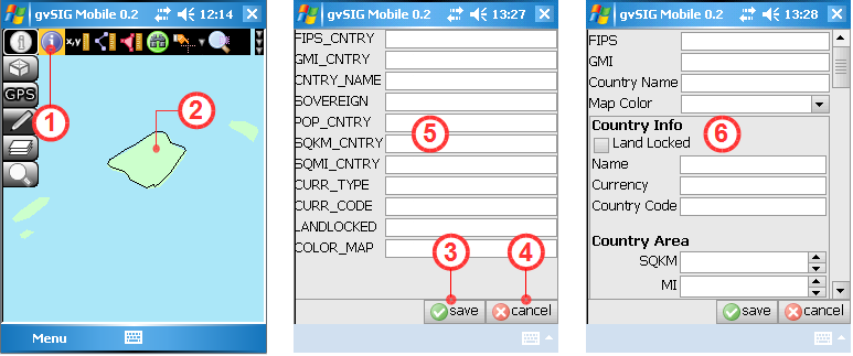
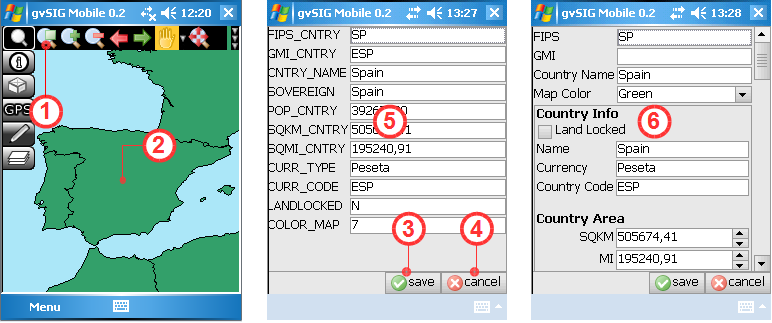
- How to Enter/Edit Attribute Values:
The following steps describe how to enter attribute values for newly created geometries and how to modify the attributes of existing geometries in the layer being edited. To edit attributes the layer must be active and editable, as described in Step 1 above. Open the Information Tools and select the Get Information tool (1) described previously in this manual. Use this tool to select a newly created geometry from the editable layer in the View (2), or select an existing geometry for which the attributes need to be updated. Selecting a geometry brings up either a Standard Form (5) or a Personal Form (6), which can be used to enter or edit the geometry's attributes. If a Personal Form (6) has been defined for the layer then this is used in place of the Standard Form (5) for both editing and viewing of attributes. When the entering/editing of attributes is complete the changes are saved by clicking the Save button (3). Clicking the Cancel button (4) will cancel any changes and revert to the previously saved attribute values. The following figures show the attribute forms for a new polygon created with the polygon tool (top) and for an existing polygon in the editable layer (bottom).
Entering attributes for a newly digitised geometry
Editing attributes of an existing geometry in the layer
- Step 4 - Save/Reject edits:
The final step is to ensure that the new geometries, their attributes and any other changes are saved permanently in the vector file on disk. This is done by returning to the TOC (1) and unchecking the Enable editing box (2). This brings up an Information Window (3) asking the user whether to save the layer or not. Clicking the OK button saves any edits permanently to disk while clicking the Cancel button causes any changes to be discarded (4). If you do not wish to overwrite the original layer then the edits can be saved in a new layer with a different filename using the Export to Vector File tool on the Layer Management toolbar described previously. This file can be exported in any of the formats supported by the Export tool.
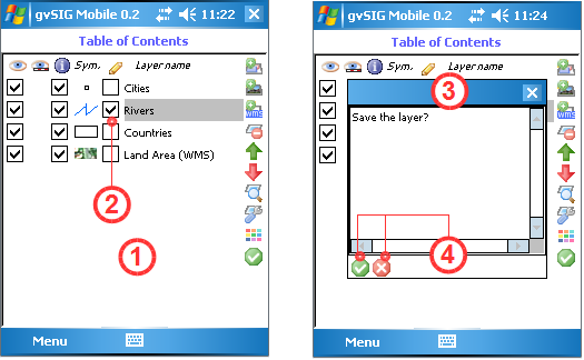
Save/Cancel the edits of the vector layer
NOTE:
There are a number of limitations when editing layers:
- The layer must be a vector layer.
- Only one vector layer can be edited at a time.
- If the original vector layer contains a single type of geometry (points, lines or polygons) then only the same type of geometry can be added.
- It is not possible to create new attributes that are not already in the layer being edited. Each new geometry only inherits attributes already existing for other geometries in the layer.
- It is not possible to modify geometries that existed in the layer before editing was enabled. However, it is possible to edit their attributes.
- To cancel any changes made since editing was enabled, simply uncheck the Editing checkbox in the TOC and click the cancel button when asked to save changes. The layer will return to the state it was in prior to any editing.
- Generating of points and track points from a GPS is only be possible if the GPS is enabled and working properly.


